Mastering CAD and CAM with Autodesk Fusion 360: A Comprehensive Guide
Introduction: Autodesk Fusion 360 is a powerful software suite that integrates computer-aided design (CAD) and computer-aided manufacturing (CAM) capabilities into a single platform, providing engineers, designers, and manufacturers with a comprehensive solution for product development and production. In this comprehensive guide, we will explore the intricacies of using Autodesk Fusion 360 for CAD and CAM, covering everything from design workflows and modeling techniques to toolpath generation and machining strategies.
Section 1: Introduction to Autodesk Fusion 360 1.1 Understanding CAD and CAM: Computer-aided design (CAD) is the process of creating digital 3D models of parts and assemblies, while computer-aided manufacturing (CAM) involves generating toolpaths and instructions for machining or manufacturing those models. Autodesk Fusion 360 combines CAD and CAM functionalities into a unified platform, enabling seamless integration between design and manufacturing processes.
1.2 Importance of Integrated CAD/CAM: Integrated CAD/CAM software like Fusion 360 streamlines the product development workflow by allowing designers to create manufacturable designs directly within the same environment where manufacturing processes are planned and executed. This integration improves collaboration, reduces errors, and accelerates time-to-market for new products.
Section 2: Getting Started with Autodesk Fusion 360 2.1 Overview of Fusion 360: Fusion 360 is a cloud-based software solution that offers a wide range of tools and features for 3D modeling, simulation, rendering, and manufacturing. It is accessible from any device with an internet connection and supports collaborative workflows, allowing multiple users to work on the same project simultaneously.
2.2 Installation and Setup: To begin using Fusion 360, users need to sign up for an Autodesk account and download the software from the Autodesk website. Fusion 360 is available for Windows and macOS operating systems, and it offers a free trial for new users, as well as subscription-based pricing options for individuals and businesses.
Section 3: CAD Modeling in Fusion 360 3.1 Creating Sketches: In Fusion 360, the design process typically starts with creating 2D sketches that serve as the basis for 3D geometry. Users can sketch shapes, lines, arcs, and curves using intuitive sketching tools and constraints to define dimensions and relationships between sketch entities.
3.2 Extruding and Modifying Features: Once a sketch is created, users can extrude it to create solid bodies or surfaces. Fusion 360 offers a variety of modeling tools for creating and modifying features such as extrusions, revolves, sweeps, and lofts. Users can add fillets, chamfers, holes, and other features to refine their designs and improve manufacturability.
Section 4: Parametric Modeling and Design Iteration 4.1 Parametric Design: Fusion 360 supports parametric modeling, allowing users to define parameters and equations to control the dimensions and behavior of their designs. Parametric modeling enables design changes to be made quickly and easily, facilitating iterative design processes and design optimization.
4.2 Design Iteration and History: Fusion 360 maintains a complete history of design changes, enabling users to revisit previous states of the design and make modifications at any point in the design process. Design iteration in Fusion 360 is non-destructive, meaning that changes can be made without losing previous design iterations or data.
Section 5: Assembly Design and Motion Simulation 5.1 Assembly Modeling: Fusion 360 allows users to create assemblies by combining multiple components and defining relationships between them. Users can constrain components with mates, joints, and motion links to simulate mechanical movement and analyze assembly behavior.
5.2 Motion Simulation: Fusion 360 includes built-in motion simulation tools that allow users to analyze the kinematics and dynamics of mechanical assemblies. Users can define motion constraints, simulate assembly motion, and visualize the movement of components to validate design concepts and identify potential issues.
Section 6: CAM Setup and Toolpath Generation 6.1 Setting Up CAM Workspaces: In Fusion 360, users can switch to the CAM workspace to define machining operations and generate toolpaths for CNC machining. Fusion 360 supports a wide range of CNC machines, including milling machines, lathes, routers, and laser cutters.
6.2 Defining Machining Operations: Users can define machining operations such as facing, contouring, pocketing, drilling, and threading using Fusion 360’s CAM tools. Each machining operation is defined by specifying the tool, cutting parameters, machining strategy, and machining region within the part or assembly.
Section 7: Toolpath Generation and Simulation 7.1 Toolpath Generation: Fusion 360 automatically generates toolpaths based on the defined machining operations and parameters. Users can customize toolpaths by adjusting parameters such as cutting speeds, feeds, stepovers, and tool engagement to optimize machining efficiency and surface finish.
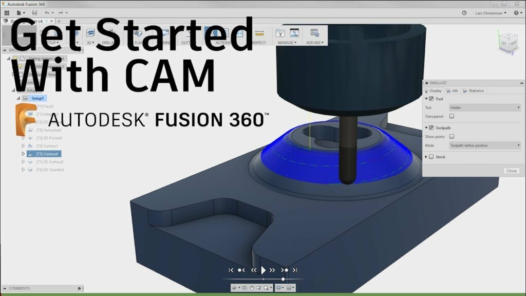
7.2 Simulation and Verification: Before machining, users can simulate and verify toolpaths within Fusion 360 to detect any potential collisions, errors, or issues. Fusion 360’s simulation tools provide visual feedback on machining operations, material removal, and machine tool movements, allowing users to identify and correct problems before sending the program to the CNC machine.
Section 8: Post-Processing and Machining 8.1 Generating G-Code: Once toolpaths are verified, Fusion 360 generates G-code, the machine-readable language used by CNC machines to control tool movement and machining operations. Fusion 360 provides post-processors for a wide range of CNC machines, ensuring compatibility and seamless integration with machine controllers.
8.2 Machining and Production: With G-code generated, users can transfer the program to the CNC machine for machining. Fusion 360 offers options for direct machine control, as well as offline programming and simulation capabilities to optimize production workflows and minimize machine downtime.
Section 9: Real-World Applications and Case Studies 9.1 Product Design and Development: In product design and development, Fusion 360 is used to create 3D models, visualize design concepts, and generate prototypes for testing and validation. Engineers and designers use Fusion 360’s integrated CAD/CAM capabilities to iterate on designs, simulate manufacturing processes, and produce functional prototypes ready for production.
9.2 Manufacturing and Production: In manufacturing and production, Fusion 360 streamlines the transition from design to manufacturing by providing a seamless workflow for CAM programming and machining. Manufacturers use Fusion 360 to generate toolpaths, optimize machining processes, and produce high-quality machined parts with precision and efficiency.
Section 10: Best Practices and Optimization Strategies 10.1 Design for Manufacturability: To optimize designs for manufacturing, users should consider factors such as material selection, geometric complexity, and machining feasibility early in the design process. Fusion 360’s integrated CAD/CAM environment enables designers to evaluate design manufacturability, identify potential issues, and make design decisions that streamline the manufacturing process.
10.2 Toolpath Optimization: To improve machining efficiency and part quality, users should optimize toolpaths by adjusting cutting parameters, selecting appropriate machining strategies, and minimizing unnecessary tool movements. Fusion 360’s CAM tools offer advanced optimization features such as adaptive clearing, high-speed machining, and toolpath smoothing to maximize machining performance and productivity.
Section 11: Future Trends and Developments 11.1 Additive Manufacturing Integration: As additive manufacturing (3D printing) technologies continue to evolve, future developments in Fusion 360 may focus on integrating additive manufacturing capabilities into the software platform. Users may be able to design for additive manufacturing, simulate printing processes, and generate toolpaths for 3D printers directly within Fusion 360, enabling seamless integration of additive manufacturing into the product development workflow.
11.2 Cloud-Based Collaboration and Simulation: With the growing importance of cloud computing and collaborative workflows, future versions of Fusion 360 may enhance cloud-based collaboration and simulation capabilities. Users may benefit from real-time collaboration features, cloud-based simulation tools, and access to shared design and manufacturing data, facilitating teamwork and communication across distributed teams and organizations.
Conclusion: Autodesk Fusion 360 is a versatile and powerful software solution for CAD and CAM, offering a comprehensive set of tools and features for product design, engineering, and manufacturing. By mastering the techniques and best practices outlined in this guide, users can leverage Fusion 360’s integrated CAD/CAM capabilities to streamline the product development process, optimize manufacturing workflows, and bring innovative products to market faster and more efficiently. With its intuitive interface, robust modeling tools, and seamless integration of design and manufacturing processes, Fusion 360 continues to be a preferred choice for engineers, designers, and manufacturers seeking to achieve excellence in product development and production.