Mastering Pneumatic System Design with Autodesk Inventor: A Comprehensive Guide
Introduction: Pneumatic systems play a crucial role in various industries, including manufacturing, automotive, aerospace, and robotics. These systems utilize compressed air to perform mechanical work, such as actuating cylinders, controlling valves, and powering pneumatic tools. Autodesk Inventor, a leading computer-aided design (CAD) software, provides powerful tools and features for designing and simulating pneumatic systems with precision and efficiency. In this comprehensive guide, we will explore the intricacies of designing pneumatic systems in Autodesk Inventor, covering everything from fundamental concepts and component selection to practical design techniques and advanced simulation strategies.
Section 1: Introduction to Pneumatic Systems 1.1 Understanding Pneumatics: Pneumatics is a branch of engineering that deals with the study and application of compressed air to perform mechanical work. Pneumatic systems consist of various components, including compressors, air reservoirs, valves, actuators, and pneumatic circuits, which work together to control and manipulate air flow for specific tasks and applications.
1.2 Importance of Pneumatic System Design: Effective pneumatic system design is essential for achieving optimal performance, reliability, and efficiency in industrial and automation applications. Well-designed pneumatic systems can improve productivity, reduce downtime, and enhance safety by providing precise control over mechanical operations and motion.
Section 2: Fundamentals of Pneumatic System Design 2.1 Basic Components of Pneumatic Systems: Pneumatic systems consist of several key components, including:
- Compressors: Devices that compress air from the atmosphere into a pressurized state.
- Air Reservoirs: Storage tanks that hold compressed air to provide a steady supply for pneumatic devices.
- Valves: Control devices that regulate the flow of air into and out of pneumatic actuators and circuits.
- Actuators: Mechanical devices powered by compressed air to produce linear or rotary motion, such as cylinders, pistons, and rotary actuators.
- Pneumatic Circuits: Interconnected network of components and tubing used to route and control air flow within the system.
2.2 Design Considerations: When designing pneumatic systems in Autodesk Inventor, engineers must consider various factors, including:
- System Requirements: Define the operational specifications, performance goals, and functionality requirements of the pneumatic system.
- Component Selection: Choose appropriate components based on application requirements, including compressor capacity, actuator type, valve configuration, and tubing size.
- Safety Considerations: Ensure proper safety measures are implemented to prevent overpressurization, leakage, and potential hazards associated with pneumatic systems.
- Space Constraints: Consider spatial limitations and installation requirements when designing pneumatic systems for specific environments or machinery.
Section 3: Design Workflow in Autodesk Inventor 3.1 Overview of Autodesk Inventor: Autodesk Inventor is a professional-grade CAD software suite that offers powerful tools and features for 3D modeling, assembly design, simulation, and documentation. With its intuitive interface and comprehensive functionality, Inventor provides an ideal platform for designing complex mechanical systems, including pneumatic systems.
3.2 Installation and Setup: To begin designing pneumatic systems in Autodesk Inventor, users need to install the software on their computer systems and configure preferences and settings according to their workflow requirements. Autodesk provides various licensing options, including perpetual licenses and subscription-based plans, to accommodate different user needs.
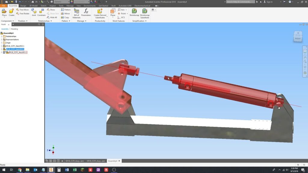
Section 4: Creating Pneumatic Components and Assemblies 4.1 3D Modeling Basics: In Autodesk Inventor, users create pneumatic components and assemblies using parametric 3D modeling techniques. By sketching 2D profiles and extruding, revolving, or sweeping them into 3D shapes, users can create cylinders, pistons, valves, actuators, and other pneumatic components with precision and accuracy.
4.2 Assembly Design: Once individual components are modeled, users assemble them into larger assemblies representing complete pneumatic systems. Autodesk Inventor’s assembly design tools allow users to constrain components, define relationships, and simulate motion to ensure proper fit, function, and interaction between parts within the system.
Section 5: Tubing and Piping Design 5.1 Tubing and Piping Components: In pneumatic systems, tubing and piping play a critical role in routing compressed air from the source to pneumatic actuators and devices. Autodesk Inventor provides tools for creating and configuring tubing and piping components, including straight sections, elbows, tees, connectors, and fittings, to build pneumatic circuits and networks.
5.2 Routing and Layout: Users can route tubing and piping within pneumatic assemblies using Autodesk Inventor’s routing functionality. By defining paths, specifying routing preferences, and adding fittings and accessories, users can create efficient and organized pneumatic layouts that minimize pressure drop, optimize flow distribution, and ensure proper clearance and accessibility.
Section 6: Valve Selection and Control 6.1 Valve Components: Valves are critical components in pneumatic systems that control the flow of compressed air to actuators, cylinders, and other pneumatic devices. Autodesk Inventor provides a library of standard valve components, including solenoid valves, directional control valves, check valves, and proportional valves, which users can incorporate into their designs.
6.2 Valve Control and Actuation: Users specify valve configurations and control methods within pneumatic assemblies to regulate air flow and actuate pneumatic devices. Autodesk Inventor allows users to define valve states, assign control signals, and simulate valve operation to verify system functionality and performance under different operating conditions.
Section 7: Simulation and Analysis of Pneumatic Systems 7.1 Static and Dynamic Analysis: Autodesk Inventor offers simulation capabilities for analyzing the static and dynamic behavior of pneumatic systems. Users can perform static stress analysis to evaluate structural integrity and reliability, as well as dynamic motion analysis to simulate the operation and response of pneumatic actuators and mechanisms.
7.2 Flow Simulation: Inventor’s flow simulation tools enable users to analyze air flow and pressure distribution within pneumatic circuits and components. By simulating fluid dynamics, users can identify flow restrictions, optimize tubing layouts, and ensure uniform air distribution to pneumatic actuators and devices for optimal performance.
Section 8: Documentation and Visualization 8.1 Technical Drawings and Documentation: Autodesk Inventor allows users to create detailed technical drawings, schematics, and documentation for pneumatic systems. Users can generate 2D drawings, bill of materials (BOM), and assembly instructions to communicate design specifications, part lists, and assembly procedures to stakeholders, manufacturers, and assembly teams.
8.2 Visualization and Rendering: Users can visualize pneumatic systems in Autodesk Inventor using realistic rendering and visualization tools. By applying materials, textures, and lighting effects, users can create lifelike renderings and visualizations of pneumatic assemblies, showcasing design concepts, aesthetics, and functionality in presentations and proposals.
Section 9: Optimization and Iterative Design 9.1 Design Optimization: To optimize pneumatic systems for performance, efficiency, and reliability, users can iterate on design concepts, refine components, and optimize system parameters using Autodesk Inventor’s parametric modeling capabilities. By analyzing simulation results, users can identify design improvements, implement changes, and validate performance enhancements through iterative design iterations.
9.2 Design Validation and Verification: Autodesk Inventor facilitates design validation and verification through simulation and analysis tools that assess the functional, structural, and performance aspects of pneumatic systems. Users can verify design integrity, compliance with specifications, and adherence to safety standards to ensure that pneumatic systems meet design requirements and performance objectives.
Section 10: Real-World Applications and Case Studies 10.1 Manufacturing Automation: Pneumatic systems designed in Autodesk Inventor are widely used in manufacturing automation applications, including assembly lines, material handling, and robotics. These systems provide precise control over pneumatic actuators and devices to perform repetitive tasks, manipulate workpieces, and enhance production efficiency and throughput.
10.2 Industrial Machinery: In industrial machinery and equipment, pneumatic systems play a critical role in powering mechanical operations such as clamping, lifting, and positioning. Autodesk Inventor enables engineers to design custom pneumatic systems tailored to specific machinery requirements, optimizing performance, reliability, and safety in industrial environments.
Section 11: Future Trends and Developments 11.1 Integration with IoT and Industry 4.0: As industry trends towards automation, connectivity, and smart manufacturing, future developments in Autodesk Inventor may focus on integration with Internet of Things (IoT) and Industry 4.0 technologies. Users may benefit from IoT-enabled pneumatic systems that communicate sensor data, monitor performance, and adapt to changing operating conditions in real-time for improved efficiency and productivity.
11.2 Advanced Simulation and Analysis: With advancements in simulation and analysis capabilities, future versions of Autodesk Inventor may offer enhanced tools for simulating complex pneumatic systems, including multi-physics simulations, fluid-structure interaction, and coupled analysis with other engineering disciplines. Users may have access to advanced simulation features for predicting system behavior, optimizing performance, and mitigating design risks in pneumatic system design.
Conclusion: Autodesk Inventor provides engineers and designers with a comprehensive platform for designing pneumatic systems with precision, efficiency, and reliability. By mastering the techniques and best practices outlined in this guide, users can leverage Autodesk Inventor’s powerful tools and features to create innovative pneumatic designs, optimize system performance, and bring their pneumatic system concepts to life. With its intuitive interface, robust modeling capabilities, and seamless integration with simulation and analysis tools, Autodesk Inventor continues to be a preferred choice for pneumatic system design in various industries and applications.