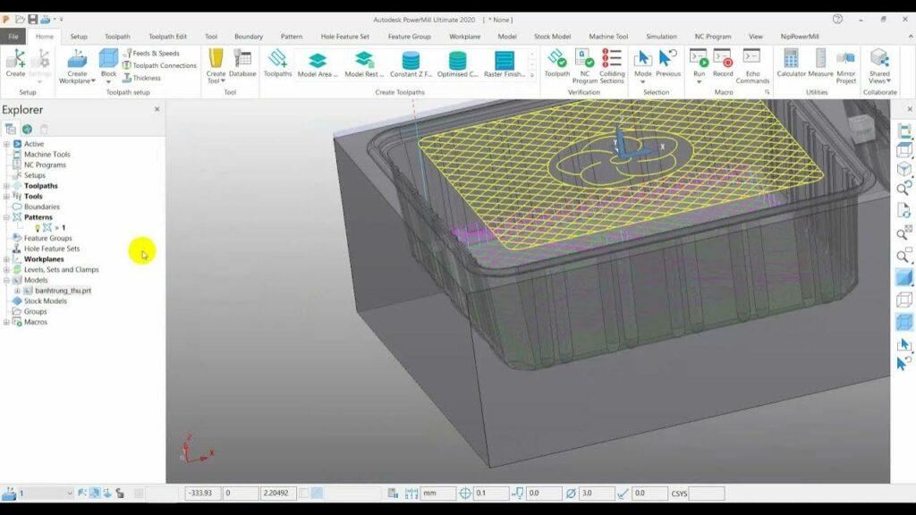
Unlocking Precision: A Step-by-Step Guide to Importing CAD Models into PowerMill Ultimate

Importing CAD models into Autodesk PowerMill Ultimate is a fundamental step in the process of generating toolpaths for CNC (Computer Numerical Control) machining. PowerMill Ultimate, a leading CAM (Computer-Aided Manufacturing) software, empowers users to create intricate machining strategies based on 3D CAD (Computer-Aided Design) models, enabling precise and efficient manufacturing processes. In this comprehensive guide, we will explore the detailed process of importing CAD models into PowerMill Ultimate, covering various methods, file formats, and considerations to ensure seamless integration and accurate machining operations.
1. Launching PowerMill Ultimate:
- Begin by launching the PowerMill Ultimate software on your computer. Double-click on the desktop shortcut or access it from the Start menu to open the application.
2. Creating a New Project or Opening an Existing Project:
- Upon launching PowerMill Ultimate, you have the option to create a new project or open an existing project. If you’re starting a new project, follow the prompts to set up project parameters, including project name, location, units, and machine configuration.
3. Importing CAD Models:
- Once the project is created or opened, navigate to the File menu and select the “Import CAD Model” option. Alternatively, you can use the shortcut keys or toolbar icons to access the import function.
- In the import dialog box, browse to locate the CAD file you wish to import into PowerMill Ultimate. Supported file formats for import include STEP, IGES, Parasolid, SAT, STL, and more.
- Select the desired CAD file and click “Open” to initiate the import process. PowerMill Ultimate will analyze the CAD geometry and import it into the project workspace.
4. Adjusting Import Settings:
- Depending on the complexity and size of the CAD model, you may need to adjust import settings to optimize performance and accuracy. Common import settings include units, tolerance, and geometry conversion options.
- Specify the units of measurement (metric or imperial) to ensure consistency between the CAD model and PowerMill Ultimate. Adjust tolerance settings to control the level of detail and accuracy in the imported geometry.
- Explore geometry conversion options such as simplification, healing, and merging to optimize the imported CAD model for machining operations.
5. Reviewing Imported Geometry:
- After the CAD model is imported into PowerMill Ultimate, review the imported geometry to ensure accuracy and completeness. Navigate through different views and sections of the model to inspect details and identify any issues or anomalies.
- Use visualization tools such as zoom, pan, and rotate to examine the imported geometry from different perspectives. Check for missing surfaces, gaps, or errors that may require further attention.
6. Organizing CAD Models within the Project:
- Organize imported CAD models within the project workspace to streamline workflow and facilitate collaboration. Create folders or groups to categorize CAD models based on their purpose, components, or assembly structure.
- Rename CAD models with descriptive names to distinguish between different components or versions of the design. Maintain a logical hierarchy and file structure to ensure easy access and management of project assets.
7. Verifying Compatibility and Interoperability:
- Ensure compatibility and interoperability between the imported CAD model and other project elements such as toolpaths, machining strategies, and simulation setups. Verify that the imported geometry aligns with project requirements and design specifications.
- Address any discrepancies or inconsistencies between the CAD model and machining environment, such as differences in units, scale, or orientation. Make necessary adjustments to ensure seamless integration and accurate machining operations.
8. Saving the Project:
- Once the CAD model is imported and reviewed, save the project to preserve the imported geometry and associated project settings. Choose a descriptive name for the project file and specify the location where it will be saved on your computer.
- Saving the project ensures that all imported CAD models, toolpaths, and project configurations are stored securely and can be accessed and modified as needed in future sessions.
9. Accessing Imported CAD Models for Machining:
- With the CAD model successfully imported into PowerMill Ultimate, you can now proceed to create toolpaths, define machining strategies, and simulate machining operations based on the imported geometry. Utilize the imported CAD model as the foundation for generating precise and efficient toolpaths for CNC machining.
Conclusion:
- Importing CAD models into Autodesk PowerMill Ultimate is a critical step in the CAM workflow, enabling users to leverage 3D CAD geometry for generating toolpaths and simulating machining operations.
- By following the step-by-step guide outlined above, users can seamlessly import CAD models into PowerMill Ultimate, adjust import settings, review imported geometry, and organize project assets to optimize workflow efficiency and accuracy.
- Embrace the capabilities of PowerMill Ultimate to unlock the full potential of imported CAD models and embark on a journey of precision and innovation in CNC machining.


